
Weld inspection

The top priority in welding is the quality of the weld. Welding specialists and robot welding systems alike are measured against this. In the automotive industry in particular, the quality standard is very high. The consequences of weld defects immediately cause production and rework costs to shoot up – and in the worst case, human lives could even be at stake.
In this e-book we present the different methods of weld inspection, show their fields of application as well as their advantages and disadvantages, focus on robot-supported optical weld inspection and explain this in detail.
Ultimately, it is your decision which testing method is best suited to your automated application.
... or scroll down to read the complete guide.
Enjoy!

Jan Neubert
Head of Laser Technology, Alexander Binzel Schweisstechnik GmbH & Co. KG
Jan Neubert is Head of Laser Technology in the ABICOR BINZEL LASER SYSTEMS division of Alexander Binzel Schweisstechnik GmbH & Co. KG and has been involved in the process-side development, optimisation and automation of various joining processes for almost 25 years. His focus is on the use of laser beams as a tool for both joining and inspecting seams.

Bernd Lorösch
Head of Weld Inspection Systems, SmartRay GmbH
Bernd Lorösch is responsible for the Weld Inspection Systems division at SmartRay and has over 25 years of experience in the field of production-integrated, optical, robot-supported 3D quality inspection. His focus is particularly on data-supported process optimization with the aim of creating more efficient and more sustainable welding processes.
The joining of components – whether by means of inert gas welding, laser welding or laser brazing – always involves a certain risk: every joint must be secure and also look good after application. Defective seams can lead to porosity, for example, be unstable and in the worst case endanger human life. Defects in visible seams can reduce the value of a component in further processing and lead to recall processes involving expensive rework.
There are different defects that can occur during robot welding. It is annoying when these defects are not detected and rectified before the component moves on to the next production step.

- Non-welded seams
- Incompletely welded seams
- Cracks or pores in the welds
- Seams not continuously welded
- Incompletely filled weld groove
- Undercut
- Weld spatter
All these weld defects can influence the stability and the tightness of a component. If too little filler metal – in other words welding wire – is introduced into the joint to be welded, the weld cross-section is not sufficient. If the weld melts at the side – this is known as undercut – this is not a weakening of the weld itself but rather a weakening of the lateral material, a burn-in to the metal structures. Cracks and pores in the weld weaken the flow of forces and may also reduce the cross-section, which is a double restriction on the structural load-bearing capacity.
Interestingly enough, the length of the weld is usually longer than what may be required for risk seams. For example, if a 20 mm load-bearing length is required for a weld, we typically see a 25 mm weld applied. This would be considered a good seam and tolerated since this would not impact the integrity of the load-bearing capacity.
With risk seams a distinction is made between:
- structurally important seams
- optically relevant seams

Structurally important seams
The classification "structurally important seams" covers welds which are essential for the structural integrity of a component. Examples of these are truck frames, cross members, chassis or vehicle undercarriages. Defects in the weld mean a direct risk of property damage and personal injury. In e-mobility, which is a market with strong growth, every manufacturing company wants to and must be on the safe side. Everyone is familiar with horrific pictures of vehicles on fire. It depends on the tightness of the battery box whether the occupants can leave the vehicle in time before the chemical substances escape from the battery and cause a fire. However, not only defective welds on battery boxes but also weld spatter on the sealing areas and thus lack of positive fit can trigger leaks.

Optically relevant seams (visible seams)
The classification "visible seams" refers to welds on components which have to have a consistently attractive appearance. Examples of this are vehicle frames, roof seams on vehicles or frames on furniture such as tables, shelves, beds etc. Even if the focus is not on stability in the case of optically relevant seams, recalls can still occur. If a roof seam on a vehicle has not been welded correctly, for example, and is then painted without a subsequent weld inspection, the rework through grinding, correction and repainting will be much more expensive. This does not even take the customer’s annoyance and possible future loss of revenue due to loss of image into account.
For both structurally important seams and optically relevant seams – the return on investment (ROI) is very attractive if weld defects are identified and can be reworked quickly before the further processing of components.
More on this in "Payback calculation for the implementation of optical weld inspection".

Weld inspections are mainly used wherever structurally important components have to be joined together; these are responsible for the safety, stability and quality of the finished product. Weld inspection is used in various industrial areas:
- Plant and power station construction
- Oil and gas industry
- Steel and mechanical engineering
- Shipbuilding
- Vehicle construction
Defects in the weld can have fatal consequences for plants, structures, people and the environment. More and more manufacturing companies in industry and trade are obtaining certification in order to guarantee the proper manufacturing of their products and meet their customers’ requirements.

DIN EN ISO 3834 – Quality requirements for fusion welding of metallic materials
Defines criteria for the manufacturers of components and structures with fusion-welded joints in series production, individual production, repairs and assembly.
DIN EN ISO 1090
Regulates production control for load-bearing steel and aluminum components which enter the market as construction products.
Weld inspection ensures that the welding work has been carried out properly and fulfils its function completely.
There are different approaches to inspecting a weld. However, if you consider that weld inspections have to guarantee the safety of structure-relevant components, some of the methods of weld inspection that we present briefly below can be disregarded. If the safety of structure-relevant components is specified, it is imperative to be able to document the acquired data 100 percent as results and rectify defects in the weld as quickly as possible. This is only possible by intervening quickly as soon as a defect has been detected.
| Testing method | Speed | Possibility of automation | 100 % inspection | For MIG/MAG-applications | For laser applications | Costs |
| Visual inspection | ↓ | ✖️ | ✖️ | ✓ | ✖️ | ↑ |
| Ultrasonic | ↓ | ✖️ | ✖️ | ✓ | ✖️ | ↓ |
| X-rays | ↓ | ✓ | ✖️ | ✓ | ✓ | ↓ |
| Dye penetration method |
↓ | ✖️ | ✖️ | ✓ | ✖️ | ↑ |
|
Magnetic |
↓ | ✖️ | ✖️ | ✓ | ✖️ | ↑ |
| Micrographs | ↓ | ✖️ | ✖️ | ✓ | ✓ | ↓ |
| OCT | ↑ | ✓ | ✓ | ✖️ | ✓ | ↓ |
|
Optical weld |
↑ | ✓ | ✓ | ✓ | ✓ | ↓ |
High = ↑ Low = ↓ Possible = ✓ Not possible = ✖️

All these methods are basically carried out in the following sequence:
- Inspect seam
- Recognise irregularities
- Measure size/position of the irregularities
- Compare size/position of the irregularities for permissibility with normative
- Decision size/position of irregularities permissible
→ Seam OK - Decision size/position of irregularities not permissible
→ Defect and seam not OK

Implementation:
Visual inspection is a method of non-destructive testing (NDT). Following the welding process, an inspector looks at the welds on a welded component. Inspection criteria include e. g. sufficient length, thickness or height of a weld, which can be checked for correctness through visual inspection by a trained eye.
Advantages:
- Low initial investment
- Can be used anywhere in the process flow
Disadvantages:
- Very slow method
- Only suitable for looking for defects on the surface
- Insufficient precision for most requirements
- Physically very tiring, time pressure, no 100 % guarantee of finding defects
- Good or sufficient documentation cannot be guaranteed

Implementation:
Ultrasonic defect detectors are placed next to the weld and, like visual inspection, make non-destructive testing possible. High-frequency sound waves are conducted through the welded sheet metal. If the signal deviates from its regular propagation, this indicates that a defect has been detected.
Advantages:
-
Very good penetration depth compared with other non-destructive testing methods
-
Also recognizes defects which the human eye cannot perceive
-
Inner defects (pores, cracks, inclusions) can also be detected
-
Portable and cost-effective device compared to other inspection methods
Disadvantages:
-
Complex testing method
-
Requires highly qualified inspectors
-
Cannot be automated, still requires a further subsequent inspection process

Implementation:
Weld inspection with X-rays is a so-called X-ray coarse structure examination, which is another non-destructive testing method. Here, a photographic record of the transmitted energy is generated with the aid of X-rays and gamma rays which are introduced to the component, scatter in it and are absorbed. Since irregularities such as pores, cracks or inclusions have different densities compared with the base material, these can be shown on an X-ray image.
Advantages:
-
Inner weld defects are also detected
-
Makes the shape and size of the defects visible
-
Can be automated to a certain extent
Disadvantages:
-
Difficult to determine the depth of the defect, cracks are only detected through a targeted search
-
High time and equipment expenditure
-
Only limited material thicknesses can be tested

Implementation:
The dye penetration method is another non-destructive seam testing method. A dyed or fluorescent fluid is applied to the surface of the workpiece to be tested. Cavities, cracks or other flaws allow the test fluid to penetrate due to their capillary effect. The remaining test fluid is removed and a so-called developer layer is applied. The residues of the heavily contrasting dyed penetration agent become visible on the surface due to the counter-capillary effect of the developer layer and allow the defective spots to be detected.
Advantages:
-
Makes cracks, pores and bonding defects up to 1 µm clearly visible
-
Portable device, low-cost method for the simple detection of surface defects
Disadvantages:
-
Requires very thorough and careful implementation by qualified personnel
-
Cannot be automated
-
Slow testing process which still requires a further subsequent test step

Implementation:
The magnetic powder test – likewise a non-destructive seam testing method – can detect cracks in welds close to the surface in magnetic components. If the workpiece is not magnetic, it is magnetized artificially at the point to be tested. Magnetic powder particles applied to it adhere more strongly to cracks than other areas due to an increased polar effect and provide an indication of defects in or near the component surface.
Advantages:
-
Even the tiniest of surface defects can be detected
-
Low-cost equipment
Disadvantages:
-
Deep weld defects are not detected
-
Sensitivity decreases with the size of the defect
-
Very slow testing method

Implementation:
Micrographs are a destructive weld inspection method. They are carried out at regular intervals – once a shift, once a day, once a week etc. depending on user specifications – for the purpose of auditing and for analyzing process problems. The component is cut or etched to make sure that the manufacturing process is running smoothly or to find process faults.
Advantages:
-
Provides an unrivalled clear picture of the welded seam in the area tested
Disadvantages:
-
Irreversible destruction of the component tested
-
The result cannot be seen as the sum of the whole
-
Complex and expensive procedure

Implementation:
Optical coherence tomography (OCT) is a testing process that runs in parallel to the welding process, whereas most other testing processes are downstream. OCT is a singlepoint high-speed distance measurement and an imaging process. This means that the superposition or interference of waves is used to determine quantities to be measured. An OCT scanner scans the surface of the component using a measuring laser beam and compares the results with a reference laser beam. The interference pattern generated from this combined with the deflection of the OCT measuring beam allows height profiles to be recorded.
Advantages:
-
Fast testing method
-
Test in real time
-
No contact with the sample
Disadvantages:
-
Porosity in the tenths of a millimeter range is no longer clearly visualized
-
Every laser welding robot system requires its own OCT system
-
Only measures surfaces and keyholes

Implementation:
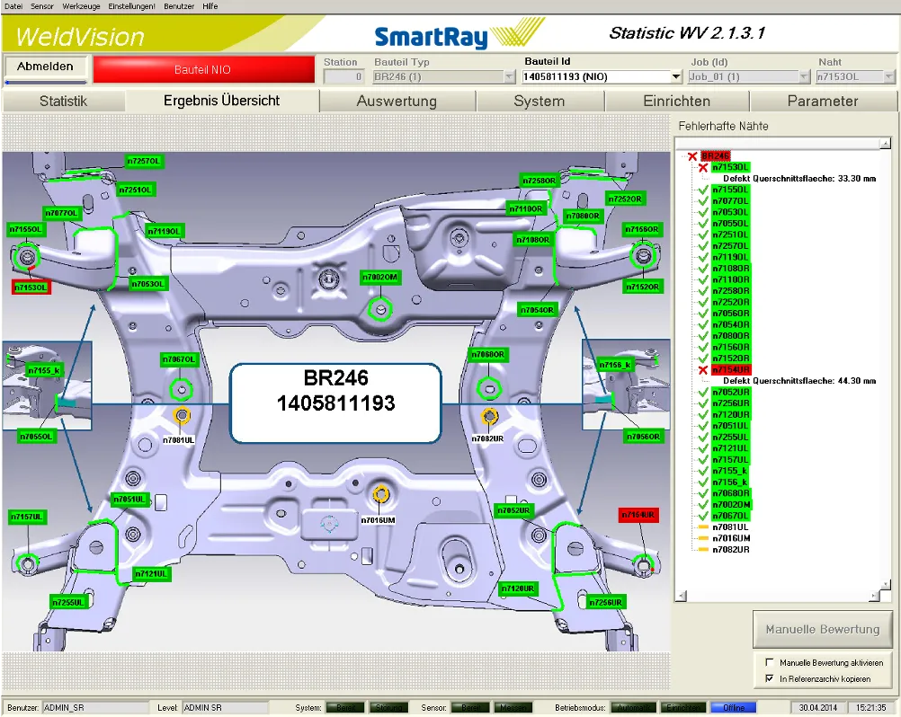
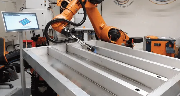
Robot-supported optical weld inspection is a testing method downstream from the welding process and part of the quality and process checks for series processes. With the aid of a camera and an integrated sensor, the weld is measured in three dimensions in real time on the basis of the laser triangulation method and turned into a 3D image using thousands of data points. The geometry captured is compared with tolerances. This allows for weld topography, weld toes, cross-section areas, weld spatter, porosity, undercut, and other defects to be detected and visualized within the software.
Advantages:
-
Automated (100 % inline)
-
Test, analysis and statistic software in one
-
Even works with highly reflective surfaces
-
Test stations can always be linked to one another, providing an overview of the status of the complete production line at all times
-
Even areas of a component that are difficult to access are inspected
Disadvantages:
- High initial investment

Obviously, that optical weld inspection is the most suitable testing method if:
→ the safety of components or their appearance have to be guaranteed
→ the test results have to be documented continuously
→ the process has to be suitable for high-speed automation
→ process optimizations are required
Optical weld inspection is a so-called opto-electronic process which can convert light energy to electronically generated data – and vice versa. With optical weld inspection, a weld is measured in three dimensions (3D) and tested objectively in accordance with applicable standards. On the basis of defined specifications, it can then be determined which facets of the tested weld fulfil the given requirements and which do not.

How the 3D inspection works on the basis of laser triangulation
Laser triangulation is based on the concept of reflecting and absorbed light. A transmitter such as a laser diode in a sensor head projects a laser line onto the workpiece. From there, the laser line is diffusely reflected and picked up by a receiver – a so-called CMOS sensor, or Complementary Metal Oxide Semiconductor – and put together in a 2D profile section. This image is created based on the sensor’s calibration, its distance to the process, its angle of inclination and moving speed and is transferred to a set of data points. These signals can be transmitted and interpreted in real time, comparable with the use as an optical seam tracking sensor.
With optical 3D weld measurement, the 2D profile sections are then placed next to one another to create a precise three-dimensional surface-based model of the scanned welds which can then be measured objectively according to international standards.
A quality and process analysis tool – and what it can do
The sensor-based or optical weld inspection can inspect the joining processes most often practised. Such applications are components welded using the MIG/MAG method, which is certainly due to their simple automation and the materials often used. However, optical weld inspection is also very suitable for testing components that have been produced using the TIG or plasma method or by laser brazing or laser welding, resistance welding or other mechanical bonding methods such as gluing.

With the help of optical weld inspection, an objectively verifiable weld quality can be guaranteed. This in turn opens up the opportunity of using less destructive testing methods, which are time-consuming on the one hand and involve high scrap costs on the other. In addition, the amount of unnecessary rework is reduced by optical weld inspection.
For every weld inspected, an OK/NOK decision is made and then sent by field bus to the robot and the PLC. What happens next to the tested component is a step stored in the welding process: If it is OK, it is forwarded to the next processing step. If it is NOK, it is transferred to the reworking process. If rework has to be done, the system can be coupled to an interactive work-station at the repair shop. The repair worker is guided straight to the welds which require reworking. Once completed, the repair work is noted in the system and the workpiece is returned to the production flow.
Which components are part of an optical weld inspection system?
An optical weld inspection system is made up of the following three main components:
- Laser triangulation sensor
- Controller
-
Analysis software
The laser triangulation sensor detects the components to be tested. Sensor manufacturers offer different versions of their sensors which differ in terms of key variables such as field of vision, resolution and operating distance. The sensor resolution is decisive for the size of the defect that can be detected in relation to the speed of the process. A low sensor resolution combined with a high process speed means that only coarse defects can be captured.
It is important to choose the capacity of the optical weld inspection system to match the testing requirements, or else defects may be missed. In addition, there is a risk that cycle times might not be kept since you have to scan more slowly than required. The following can be taken as a reference:
Speed of a modern sensor for inspecting MIG welds =130 – 200 mm/s

A fast sensor can even reach speeds of up to 400 mm/s depending on the application.
The controller represents the "run-time" unit of the system and is responsible for the communication with robots and PLC (programmable logic controller) as well as evaluating the data of the productioncritical inspection systems. The controller also often provides an embedded PLC to support the further transmission of associated data. The data transmitted by the sensor is processed in the controller and saved in the database. High-quality systems have the possibility of controlling up to two stations with one controller. In addition, they allow several systems to be linked via a central cross-line quality control station or statistics PC.
The analysis software "translates" the 3D data recorded using mathematical algorithms in order to precisely record weld limits and derived from this, to compare seams dimensionally against standard-based tolerances. It also reliably detects weld defects. Additional software packages may include:
-
PC remote support – for a direct connection to the controller, which makes an interface and communication possible across several applications.
- Visualization packages – used at repair stations, these display images of the tested component as well as OK /NOK messages for each weld. This provides direct interaction with the repair station to verify that the part has been repaired and is ready for further processing.
-
Data analysis packages – can correlate data around specific welds or parts so that the primary cause of defects can be checked, eliminated and manufacturing processes can be improved. Reports can use graphical elements such as bar charts for visualization and analysis.
Incorporation of an optical weld inspection system in the quality testing and rework assurance process
The implementation of an automated weld inspection is not easy and requires a high level of expertise among integration and supervision personnel. What always has to be taken into account: an objective inspection system integrated in the production process that compares 100 % of seams over 100 % of the seam length with standard-based tolerances can have a significantly higher defect detection rate than a visual inspection or sporadic micrographs at individually defined seam positions. In this case, it makes sense to adapt tolerance management to the automated testing method. A high-quality inspection system supports this through flexible, sometimes automated process-based tolerance ranges, in other words upper and lower limits for measured values. This makes a targeted "running in" of new manufacturing processes possible. This means that information from the testing and inspection leads to optimization of the processes. This results in small defect sizes and a necessary adaptation of the tolerance ranges to this situation.
The following list illustrates the range of elements which can be tested using the system of optical weld inspection.

Geometric test criteria
-
Length
-
Width
-
Throat thickness
-
Cross-section
-
Connection angle
-
Position
-
Asymmetry and leg dimension
-
Concavity, convexity

Welding defects that can be visualised
-
Pores (macro-pores, micro-pores, porosity such as e. g. pore nests)
-
Weld spatter
-
Holes, burn-through
-
Notches
-
Incomplete welds
-
Defective weld toes
-
Weld reinforcements
-
Incompletely filled groove
-
Non-filled end craters
Each of the points listed requires a set of objective criteria on the basis of which the tested parts are measured. What initially sounds trivial ultimately depends on the extent of correlation of the following:
→ what the human eye perceives as OK
→ the analytical values provided by calibrated sensors
The system of optical weld inspection detects defects that the human eye cannot see and precisely records dimensional deviations in particular.

Automatic optical weld inspections are mainly used wherever structurally important components have to be joined together; these are responsible for the safety of the finished product. Particularly in the automatic production of large quantities, process problems occur very quickly but can be remedied quickly through direct subsequent testing, thus keeping the costs incurred within limits. The main area of application is primarily in the automotive industry, and here strongly growing in the e-mobility sector. Weld inspections are also used as part of the quality testing in the manufacture of yellow goods, too – in other words machines for all kinds of earthwork, such as excavators or caterpillars, as well as machinery for the agricultural industry – as well as for transport and haulage vehicles and in pipeline construction.

Every vehicle launched on the market is subject by the Euro NCAP – New Car Assessment Programme – to a manufacturer-independent crash test and assessed in terms of safety for adult occupants, safety for children, pedestrian protection and supporting technical safety systems. Every defective weld can have serious consequences for road safety and demonstrably defective components can result in very high claims for damages. Not to mention human suffering.
Of course, a system for optical weld inspection is an additional investment. However, the costs of rework due to a fault in the production process being recognized too late, recalls, recourse claims and image loss on account of annoyed customers can be significantly more expensive, or even unpayable. The following checklist provides an overview of whether optical weld inspection pays for a production process.
| Situation | ✓ |
|
You produce components with high safety requirements |
|
|
You produce components that have to fulfil high quality standards |
|
|
You produce serial goods |
|
|
Your welding processes are automated to a major extent |
|
|
Complete traceability must be guaranteed |
|
|
Parts of the welded seams are very difficult to check manually or visually |
|
|
Concealed weld areas at the end of the process make more targeted weld inspection necessary |
|
|
You often recognize series defects very late |
|
|
Your rework costs are too high |
|
|
You have to expect a risk of downstream quality costs (warranty/recall) |
|
|
You see potentials for savings through data-based process optimization |

If you are frequently confronted with these or comparable situations, which ultimately result in high costs, it is worth considering optical weld inspection.
One main area of application for optical weld inspection is vehicle production: a 100-percent automated quality check is required for the welding of vehicle doors, tailgates, seats, battery boxes, hairpins, cross members, suspension arms etc.
The manufacturing of automotive supplier parts is ideally suitable for automatic weld inspection because:
-
a manual inspection is difficult to achieve with fast cycle times
-
the inspection is objective and independent of human factors
-
left undetected, a poor weld can soon cause high follow-on costs such as e. g. for recalls
-
users demand objectively measured, traceable quality checks
-
the data acquired helps to optimize the entire production process
Consequences of defective welds
Every defective weld means rework. Any defect detected too late in the production process inevitably leads to this defect being continued until it is detected. Since a component is quickly passed on to the next production step in production lines, a defect detected too late can cause even more costs than "just" the correction of a weld.
If weld defects are not detected, especially in safety-relevant components, this can cause serious problems for the manufacturer. Recourse claims or even personal injury can quickly cause unnecessary expenses.
Automated weld inspection helps the user to ensure objectively verifiable weld quality and opens up the possibility of using less destructive testing methods. In addition, the amount of unnecessary rework is reduced.
Different testing methods using optical weld inspection – a comparison
There are only a few testing methods that use optical weld inspection. We have put together a comparison of the main ones here for you.
Evaluation of the "Costs" column
The costs for the respective testing method must be considered from two angles. For automated systems, the investment costs are high, while the running costs are significantly lower due to the high testing speed and low intervention by the line operator. Thus, for example, a low-skilled employee can supervise several test stations in parallel.
Visual inspection by humans does not involve a huge investment. However, the running costs for highly qualified inspection personnel are at a consistently high level. These running costs must then be broken down in the calculation to the number of parts tested. The larger the testing volume, the earlier the return on investment.
| Testing method |
Speed |
Possibility of auto-mation | 100 % inspection | For MIG/MAG applica-tions | For laser applica-tions | Costs* |
| Visual inspec- tion |
↓ | ✖️ | ✖️ | ✓ | ✖️ | ↑ |
|
Visual |
↓ | ✖️ | ✖️ | ✓ | ✖️ | ↑ |
| OCT | ↑ | ✓ | ✖️ | ✖️ | ✓ | ↓ |
|
Optical weld |
↑ | ✓ | ✓ | ✓ | ✓ | ↓ |
High = ↑ Low = ↓ Possible = ✓ Not possible = ✖️
* see evaluation of the "Costs"
Another cost advantage for automated inspection systems is that the visual display of the defect position and defect size enables more targeted and efficient rework than is comparatively feasible with visual inspections.
For an exact ROI calculation, please see chapter "Payback calculation for the implementation of optical weld inspection".
Main advantages of sensor-based optical weld inspection
→ Holistic control of the inspection process
→ More than 99 % accuracy
→ Faster and more accurate than visual inspection done by humans
→ Data acquisition used as reference and for determining problems
→ 100 % inline inspection i. e. every seam on every part is inspected and assessed in relation to the respective requirements
→ Reduces the number of destructive tests such as sections or etching
→ Increases efficiency and reduces costs
The following criteria can be tested using sensor-based optical weld inspection:

Welds to be inspected that are difficult to access
The structure of workpieces is not always ideal for sensor-based or optical seam inspection. In spots that the slim front end of a welding torch can easily reach, the somewhat wider heads of sensors have more difficulties. Components that are clamped deeply or located in niches as well as slim components can usually not be inspected by the sensors currently available on the market. If a component has 300 welds, of which only 295 can be inspected, another solution is required.
In the meantime, there is an inspection sensor on the market that offers the same accessibility as a MIG/MAG welding torch. You can find out more here.


The sensors used so far for weld inspection must be equipped with an interconnection adapter between the robot mount and the sensor in order to achieve the best possible accessibility of the seam to be inspected. This is not necessary with this new sensor type, since the sensor is screwed directly to the robot and thus has the shape of a welding torch. Combined with the robot torch mount and safety cut-out iCAT from ABICOR BINZEL, this new sensor is even perfectly protected against crash situations.
Advantages of this sensor development are:
- Unprecedented compact sensor head in welding torch look
→ Inspects everything that is welded
- High resolution
→ Even pores of up to 0.2 mm are detected
-
Approx. 50 % higher inspection speed compared to commercially available sensors
→ Fewer inspection systems required
- Suitable for MIG/MAG and for laser processes
→ High flexibility in use
If a component weld is inspected and found to be OK, it is forwarded to the next process step. As soon as a defect is detected by the respective system, the next step stored for this case is carried out. If this is rework, the component is usually forwarded to a reworking station. Here, welding specialists receive all the inspection data of this workpiece on an interactive visualization station and can thus target and correct the defect.
After the rework of the NOK welds, the welding specialist confirms each individual reworked position on the touchpad at the visualization station. The rework of the component is documented so that it is clear later from the documentation which defects were found during the processing step and that these were indeed reworked. This way, every step in the production process becomes transparent.
Precise fault visualization and allocation on the component optimizes rework processes
Industry 4.0 is of course an important criterion for the integration of automated and thus optical weld inspection in production lines: data from the so-called end-of-line test (EOL test) is evaluated and flows directly back into production. This way, data is continually recorded that immediately makes the effects of the measures taken visible in the process. On the basis of this dashboard, process analysis data is practically evaluated backwards and provides information on further optimization of the process. This way the different process parameters on the welding result can be understood and controlled better. Rework processes are optimized, time and costs saved, resulting in sustainable, structured and continually optimized welding processes.
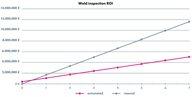
On the basis of the example of the 3D weld inspection JOSY – short for JOining SYstems – we would like to illustrate when the implementation of an optical weld inspection in your processes pays off.
JOSY improves defect detection far beyond what manual weld inspection can achieve and provides a fast return on investment (ROI). Thus, this system is more cost-effective for optical weld inspection than inspection by the human eye.
With a system for optical 3D weld inspection like JOSY, you achieve:
-
More effective logging and analysis of the data
-
Continuous optimization of the production processes
-
Longer production uptime by determining preventive maintenance requirements
Annual cost savings through JOSY
The example calculation of the annual cost savings is based on the following real initial situation:
A production line for cross members for a Tier 1 supplier in the automotive industry welds 1.000 components with 80 welds each per day. This is done in 3-shift operation on 260 production days per year. The cycle time per part is a little over one minute. These parts are sent to an OEM where they are then further processed in two plants each working in 2-shift operation.
Overview of the data:
|
Number of production days per year |
260 |
|
Number of parts produced per day |
1.000 |
|
Number of seams welded |
80 |
|
Number of working time shifts (Tier 1) |
3 |
|
Number of manufacturing OEM plants |
2 |
|
Number of shifts per OEM plant |
2 |
This example clearly illustrates that a product that has been welded by a Tier 1 supplier can be further processed at several end customer plants. This means that if quality problems occur with the first manufacturing step, several plants are affected.


To be able to inspect these 80 welds within the cycle time, JOSY is the automated weld inspection technology of choice. For this purpose, two test sensors are mounted on each of two robots at the end of the production line (EOL) – practically a double system.
The implementation of the inspection technology in the example also includes:
-
2 robots accordingly per double inspection system
-
Electric cabling
-
Programming of the robot
-
Programming of the inspection system
-
Safety enclosure
This results in a total investment of € 400.000.
This must be offset by the multiple savings that can be achieved with such an inspection system. These are made up as follows:
-
Cost reduction through less rework
-
Optimization of the production process and improvement of component quality
-
Lower claims costs
This results in the following savings for this system:
Re 1. Less rework
Even the best specialist in visual inspection of a weld can never say 100 % which weld seam actually needs reworking. Thus, components with welds that are not clearly recognizable as defective are often sent for rework even though they would be found to be OK in an automated inspection. Also, a visual inspection within the cycle times is not feasible with such a high number of welds. The cost savings of automated optical weld inspection compared to visual inspection are shown in the following comparison.
| ROI |
Automated |
Manual |
|
Rework/production costs (per year) |
€ 192.000 |
€ 579.000 |
| Total | € 192.000 | € 579.000 |
| Savings | € 387.000 | |
Re 2. Optimized production processes
But not only the rework costs can be reduced with optical weld inspection. The cost savings due to reliably running and optimized processes and thus higher plant availability are reflected in such a system:
| ROI |
Automated |
Manual |
|
Optimization of the production processes/quality Incl. longer production uptime, lower scrap costs, |
€ 147.680
|
€ 390.000
|
| Total | € 147.680 | € 390.000 |
| Savings | € 242.320 | |
Re 3. Fewer complaints
The recalls and warranty claims already mentioned are a further cost factor that must not be underestimated. Thus, these costs must also be included in the calculation of the ROI for an optical weld inspection such as JOSY. The cost savings shown below are made up of two issues:
- More minor complaints about only a few components:
A Tier 1 supplier such as in this example must carry out necessary incoming inspections directly at the OEM. With two different production lines, each with two shifts, the corresponding workers must be provided for this in the upstream shift. Such an operation can take up to three months. Usually, these services are provided by external companies. Such an assignment is rare, but occurs on average
every two years. However, the costs incurred for the Tier 1 supplier are very high.
- Major recalls:
Fortunately, serious recalls are rare, statistically once every 10 years on average. The costs involved can quickly reach several million euros. The following calculation includes the warranty costs for a damage amount of 4 million euros.
| ROI |
Automated |
Manual |
|
Average warranty costs (per year) Incl. reserves for damage limitation, recall costs, additional logistic costs |
€ 48.320
|
€ 441.600
|
| Total | € 48.320 | € 441.600 |
| Savings | € 393.280 | |
| ROI | Automated |
Manual |
|
Rework/production costs Incl. rework by specialist, overwelding (repair of non-defective welds), logistics for rework |
€ 192.000
|
€ 579.000
|
|
Optimization of the production processes/quality Incl. longer production uptime, lower scrap costs, improved quality rating |
€ 147.680 | € 390.000 |
|
Average warranty costs Incl. reserves for damage limitation, recall costs, additional logistic costs |
€ 48.320 | € 441.600 |
| Total | € 388.000 | € 1.410.600 |
| Savings per year | € 1.022.600 | |
This results in the following payback period:
| Investment JOSY | € 400.000 |
| Savings per year | € 1.022.600 |
| ROI | 0.4 years |
Calculated over the average service life of such an optical 3D weld inspection system of 7 years, the following graphical representation illustrates the cost savings for this period very well:
If you would like a personal ROI calculation for your applications, you are welcome to contact us.
Inspecting structural and chassis components such as e. g. cross members or instrument carriers
Components for the chassis or structure of a vehicle require very high demands for safety, durability and crashworthiness. Failure of a component due to defective welds can have catastrophic consequences. For this reason, the industry demands a high level of quantity in the production of these components.


The individual components are often joined using a combination of laser and MIG welding processes to ensure absolute tightness. Battery parts must be free of moisture and guarantee reliable function. Optical weld inspection technology can also be used to inspect other e-vehicle product segments such as battery cells and hairpin connectors.

Inspection of laser-brazed or laser-welded body parts (body-in-white)
Body-in-white vehicle parts in the visible area such as doors and seat assemblies are also subject to strict inspection criteria before they move onto a next manufacturing step such as painting. Correcting welding defects after painting is a very labour-intensive and costly process.
Conclusion
The high quality requirements have become an industry standard which has made weld inspection extremely important. Are you looking to prevent defective components from getting to your customer or are you trying to improve the overall process?
A high-quality automated system for optical weld inspection, which measures the quality of the weld and analyzes the process at the same time, means a high safety factor as well as a high quality guarantee for the production process – at lower costs.
We will be happy to advise and support you in bringing more safety and quality to your automated welding processes.

https://www.youtube.com/watch?v=GcU7yJmJl9Q
TH6 optical seam tracking sensor - The guide to the perfect weld seam

www.youtube.com/watch?v=vK0I17Z51Lk
Expert video TH6
Would you like to find out more about optical seam tracking solutions? Are you curious about how it could work for your production?
Then please contact one of our sales companies or the Key Account team to get to know our seam tracking solutions personally. Visit the contact page on the ABICOR BINZEL website and speak to an ABICOR BINZEL employee. Either at your premises, at one of our sales companies or at our headquarters in Buseck, Germany.
Figure right: “The eye of the robot”: The seam tracking system ensures a secure connection and a perfect seam.

We hope that you enjoyed this e-book and that your expectations have been fulfilled.
Your suggestions and comments are always welcome. Contributors to this e-book are:
Alexander Binzel Schweisstechnik GmbH & Co. KG, Germany
SmartRay GmbH, Germany
Jan Neubert,
Head of Laser Technology,
ABICOR BINZEL LASER SYSTEMS
Jan Neubert is Head of Laser Technology in the ABICOR BINZEL LASER SYSTEMS division of Alexander Binzel Schweisstechnik GmbH & Co. KG and has been involved in the process-side development, optimisation and automation of various joining processes for almost 25 years. His focus is on the use of laser beams as a tool for both joining and inspecting seams.
Bernd Lorösch,
Vice President Business Unit JOSY,
SmartRay GmbH
Bernd Lorösch is responsible for the Weld Inspection Systems division at SmartRay and has over 25 years of experience in the field of production-integrated, optical, robot-supported 3D quality inspection. His focus is particularly on data-supported process optimization with the aim of creating more efficient and more sustainable welding processes.
Alexander Binzel Schweisstechnik GmbH & Co. KG, Germany
Herbert Burbach, Art Director • Global Head of Media & Web Design | Events
Carmen Laux, Assistant Global Director Marketing
Christine Rinn, Copywriter • Media & Web Design | Content & Social Media
Melissa Haus, Marketing Specialist • Media & Web Design | Events
2024 by ABICOR BINZEL
© All rights reserved. This e-book is protected by copyright and may not be reproduced, stored or transmitted in any form or by any means, electronic, mechanical, photocopying, recording or otherwise, without the prior permission of the copyright holder.